

Diaphragm Valves Manufacturer
Home / Diaphragm Valves
What are Diaphragm Valves?
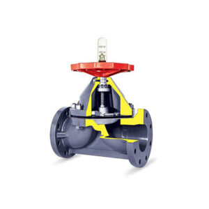
A Diaphragm Valve, or membrane valve, is a valve with an elastomeric diaphragm and a seat upon which the diaphragm rests when it is closed. The flexible diaphragm obstructs, controls, or isolates the flow of fluids and acts as a flow control device. In a Diaphragm Valve, the diaphragm element flexes up or down to increase or decrease the fluid flow rate. The valve is sealed when the diaphragm is pressed firmly against its solid seat. Diaphragm Valves are linear motion valves that monitor and control linear movement of fluids.
Diaphragm Valves are named for the flexible disc that blocks flow when it makes contact with the seat of the valve. The diaphragm is a pressure responsive component that is highly flexible and produces sufficient force to open, close, or control the function of the valve. Diaphragm Valves are like pinch valves that use a liner as part of the valve body instead of a diaphragm.

Diaphragm Valves can handle liquids, gaseous fluids, and semi-solid media such as slurries, colloids, sludges, and brackish water well. They are ideal for handling liquids with solid particulate matter. Compared to other valves, Diaphragm Valves have a simple construction. Due to the minimal contact between their internal components, the build-up of sediments and biofilms in Diaphragm Valves is very limited and does not interfere with their performance. It is for this reason that they are widely used in food and pharmaceutical manufacturing, water treatment, sewage pipelines and treatment plants, electronics manufacturing, and pulp and paper production. Taher Brothers is a reputed Diaphragm Valve Manufacturer in Kolkata, West Bengal, Odisha, Bihar, Jharkhand & all over India.
Components of Diaphragm Valves
Diaphragm Valves have a stem, bonnet, compressor, diaphragm, and actuator that are made from plastics, wood, brass, and steel. The choice of materials is dependent on the purpose and function of the valve since more durable materials are required for stressful and demanding applications.
The key component, the diaphragm, is made of flexible plastics or rubber with ethylene propylene diene monomer (EPDM) backed polypropylene plastics being the most common material and most resilient.
Bonnet
The bonnet covers the top of a diaphragm valve, is a non-wetted portion of the valve like the hand wheel and compressor, and is bolted to the body of the valve. Bonnets are quick opening and lever operated. They are interchangeable with the standard bonnets on conventional weir type valve bodies. Diaphragm valves with bonnets that are up to 10 cm are used for vacuum services. Evacuated and sealed bonnets are used for larger applications.
Bolted to the top of a diaphragm valve, the bonnet protects the compressor, stem, diaphragm, and non-wetted components.
Sealed bonnets are used with a sealing bushing for non-indicating diaphragm valves while a seal bushing and O ring are used with indicating types. The sealed type of bonnet is a necessary part of diaphragm valves that handle dangerous liquids and gasses. If there is diaphragm valve failure, hazardous substances will be sealed in the valve and not released.
Valve Body
The valve body is the component directly connected to the pipeline wherein the fluid passes through. The flow area inside the valve body depends on the type of diaphragm valve.
Both the valve body and bonnet are constructed from strong, rigid, and corrosive resistant materials.
Diaphragm
The diaphragm is made from a highly elastic polymeric disc that moves down to touch the bottom of the valve body to limit or obstruct the passage of fluid. The diaphragm lifts if the fluid flow rate is to be increased or the valve is to be fully opened. The fluid flows underneath the diaphragm. However, this component limits the valve’s operating temperature and pressure due to the diaphragm’s material and structure. It must also be replaced periodically since its mechanical properties degrade during usage.
The diaphragm isolates the non-wetted components (compressor, stem, and actuator) from the flowing media. Therefore, solids and viscous fluids are less likely to interfere with the operating mechanism of the diaphragm valve. This also protects the non-wetted components from corrosion. Conversely, the fluid in the pipeline will not be contaminated with the lubricant used in operating the valve.
Compressor
The compressor of a diaphragm valve operates the diaphragm. It is a disc with one end connected to the stem, while the other end is connected to the diaphragm. The compressor supports a diaphragm valve and distributes the forces from the stem during linear movement. It is designed to improve flow throttling and control.
When the handwheel of a diaphragm valve is turned to move the stem up or down, the motion of the stem is transferred to the compressor. As the compressor moves, the diaphragm moves upward or downward to regulate fluid flow.
Stem
The stem is a vertical shaft connected to the compressor that exerts linear motion to move both compressor and diaphragm, thus operating the diaphragm valve. It transmits the motion exerted by the actuator. Diaphragm valves can either have piston- or threaded-type stems. As the name implies, piston-type valves are moved by a piston assembly inside the bonnet, with the valve stem likely acting as the piston rod. This type requires linear force exerted by fluid pressure. Threaded stem valves have a matching stem nut. This type requires torque to linearly move the stem, as well as lubrication for smooth motion.
The threaded stems of diaphragm valves can have a rising or non-rising mechanism:
- Rising Stem Rising stems or indicating stems extend their length up to the handwheel. As the handwheel is turned, the stem rises or descends to open or close the valve, respectively. Hence, it is easier to determine the extent to which the valve is opened by looking at the amount of stem exposed. However, rising stems take up more space than non-rising stems.
- Non-Rising Stem Non-rising stems or non-indicating stems are rotated to open or close the valve, but it does not cause the stem to move up or down. Non-rising stem valves are used in limited spaces, such as in underground piping systems.
Actuator
The valve actuator is used to move the stem, the compressor, and the diaphragm altogether. It provides the torque or linear force required by the diaphragm valve to rapidly control the fluid flow rate. The actuator is dependent on the construction of the valve stem. The following are the types of actuators used in diaphragm valves.
- Manual actuators use a handwheel or a crank in which an operator applies torque. This torque is necessary to rotate the threaded stem and consequently move linearly to modify the fluid flow rate. However, these actuators have slower control speeds and require more effort to operate. Gearheads can be installed to amplify torques and enhance the opening or closing speeds. Lockability, stroke adjustment, position indication, and electrical feedback switches are the features that can be installed on manual actuators.
- Electric actuators utilize a motor in modifying the fluid flow rate. The electric motor is connected to the gear train to reduce the speed and increase the torque. These valves can operate reversibly; they can open a diaphragm valve from a closed position and vice versa.
- Pneumatic actuators utilize air pressure to move the piston inside the valve bonnet, with its piston rod connected to the compressor. Air pressure is supplied in the chamber on either side of the piston. When air is supplied in the upper chamber of the piston, it causes the piston rod to move down and lower the fluid flow rate or close the valve. Otherwise, when air is supplied in the lower chamber, it causes the piston rod to move up and increase the fluid flow rate. O-rings are present in the piston rod and the piston to prevent air leakage across both chambers. Pneumatic actuators provide fast-acting control in throttle diaphragm valves and for on and off applications.
- Hydraulic actuators utilize hydraulic fluids such as oil or water to exert a large force to open or close a diaphragm valve. These actuators are typically used in lower-speed operations.
- Thermal actuators are activated by a change in temperature in the flowing media. This activation controls the fluid flow rate.
Position Indicators
Position indicators are visual guides installed to identify the position of the diaphragm valve, whether it is in an open or closed position. It can be light, switch, or stem. Piston indicators are installed on some valves to indicate the flow direction. Terms used to describe position indicators are limit switch, beacon, position transmitter, and switch box.
The functions of valve position indicators are:
- A visual indication of valve position that makes it possible to quickly and easily determine a valve’s position and is at the top of the visual position indicator enclosure.
- Electrical feedback from internal switches, sensors, transmitters and other devices provide valve position to a PLC by sending electrical signals with the position encoded in the feedback signals.
- Local junction boxes are used to protect position switches and provide a platform to mount solenoid valves and termination points for wiring the appropriate signal wire to the enclosure.
Quick Links
- Cock Valves Manufacturer
- Stainless Steel Trap Manufacturer
- Bronze Valve Manufacturer
- Cast Iron Valve Manufacturer
- Bucket Valve Manufacturer
- Forged Steel Valve Manufacturer
- CI Water Meters Manufacturer
- Safety Valves Manufacturer
- Meter Valves Manufacturer
- Ball Valves Manufacturer
- Blow Down Valves Manufacturer
- Hydrant Valves Manufacturer
- Check Valves Manufacturer
- DRP Valves Manufacturer
- Globe Valves Manufacturer
- Gate Valves Manufacturer
- Diaphragm Valves Manufacturer
- Butterfly Valves Manufacturer